Tracing in Illustrator: description, features, types and recommendations. From raster to vector. Overview of programs for tracing raster images Tracing to vector
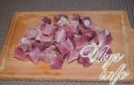
In this tutorial I will show you how to draw a realistic image of a plum using hand tracing. What it is? In general, tracing is the translation of an image from a raster to a vector. Of course, there is automatic tracing, but if you decide to learn illustrator, then you don’t really need this function. The fact is that, for example, the vast majority of stocks simply do not accept images with auto-trace: as a result, too many control points are formed, and it is simply unrealistic to edit such an image, and the size of the document increases significantly.
Manual tracing is actually a drawing lesson, when you need to trace the outline of an image and then “color” it. If you are a beginner illustrator, then this lesson will be a good practice for you in working with a pen, pencil and the MeshTool. Now let's move on to the lesson.
In Figure 1 you see a picture that is the basis of our future illustration. This is a sketch that I drew a few years ago, and now we will need it. Open the Adobe illustrator program (I have version CS5), create a new document and place our sketch there (File – Place – open the desired image on the computer). Next, we need to make this layer semi-transparent so that it is visible, but does not interfere with drawing. I do it this way: I select the image and in the Transparency panel move the Opacity slider to 30-40% (choose the most comfortable value for yourself). Figure 2 shows what should happen. So that the sketch does not interfere with our drawing, we block it. In the Layers panel, next to the layer name, there are two squares: one has an eye drawn in it, and the other is empty. So we click on the empty one; a padlock will appear in it, indicating that the layer is locked and no manipulations with the sketch are possible.

Now create a new layer (CreateNewLayer button on the Layers panel) and start drawing. You can use the PenTool or PencilTool tool. I choose a pencil because I haven’t gotten a tablet yet, and when you draw with a mouse, your hand shakes a little and the lines are unclear. When the path is created and I release the mouse button, the path is smoothed a little (smoothing parameters can be set in the pencil menu by double-clicking on this tool).
First, let's draw a branch. Our task is to create a contour. Therefore, we outline the branch visible on the bottom layer, closing the outline. The result was a kind of irregularly shaped rectangle. If you work without a graphics tablet, then your outline will be uneven to one degree or another. To align it as close as possible to the outline of the sketch, we will use the DirectSelectionTool (Partial selection). Having selected it, select the necessary anchor points one by one, which “stand out” from the overall picture, hold down the Shift key and drag them into place. The guides are also very convenient to use. In short, you need to make the copy as close as possible to the original. Something like this (Figure 3).

I don’t strive for a perfectly even contour - in the case of plums and other fruits, berries and flowers, this doesn’t make much sense. If you are tracing a human face, then you need accuracy. In the same way, we will outline the remaining elements - a leaf, two plums and two petioles. In total, we get six closed loops (Figure 4).

I will give you some useful tips. Firstly, when you edit contours, those already drawn may interfere with you when working with the next one. I recommend blocking all intersecting and adjacent objects to avoid confusion. To lock an object, click on the layer name and it will “expand”, showing all the objects that are on it. Select the ones you need and block them.
Secondly, you may have problems with the edges of the drawn contours. My recommendation in this regard is that you don’t have to bother with clearly defining the edges, but simply make the contours a little longer and hide them under the objects lying above. The only exception will be the topmost object - it must be drawn clearly. To make it clear to you, I will explain using our example. Our topmost object is the plum located on the right. The left plum seems to be under the right, so its right (excuse the tautology) edge can not be drawn clearly - it will still hide behind the top plum. You can do the same with the lower edges of the petioles (they will hide behind the plums) and with the edge of the leaf (it will hide behind the twig). I hope I explained clearly.
The third tip is about drawing plums. Instead of a pencil, it would be appropriate to use the EllipseTool. Holding down the Alt key, draw an oval in the area of the plum, approximately resembling its outline, and edit it, adding a little unevenness. Before the next step, be sure to unlock all objects.

Now we have an equally important task ahead of us - coloring our drawing. I like to use the MeshTool for this. It's not the easiest tool to use, but if you use it skillfully, you can create some very impressive images. Its main advantage is that Mesh allows you to create the effect of a three-dimensional image in two-dimensional space. First we need to give our objects primary colors. Create a fill for each object: let the leaf and petioles be green, the branch brown, and the plums purple. Choose colors that will dominate the object (see Figure 5). Then unlock the sketch layer and move it to the side so you can see it. You can also make it brighter (Opacity = 100%) (see Figure 6).

So, the MeshTool tool is, in fact, a gradient mesh, that is, a network with nodal points at the intersection of its axes. At these points, as well as in the grid cells, we have the opportunity to set any color, and the overall picture of the object converted to a gradient mesh looks like such a complex gradient.
Let's start working on the plum on the right (block the one on the left). Select its outline that you drew and click Object – CreateGradientMesh. You will see a dialog box in which you will be asked to select the number of rows and columns (Rows and Columns). Set both fields to “4” and the Appearance field to “ToCenter”, Highlight=20%.

Now you should emphasize the highlights and light and shade with color, creating the illusion of a three-dimensional object. To do this, select DirectSelectionTool and select the anchor point where you want to change the color. It will be highlighted (shaded while the others remain uncolored) as in Figure 7. Now you can apply color to it. I take a pale pink, almost white color. I do the same with a nodal point at the bottom right (see Figure 8). These are our highlights.

Then, in the same way, focusing on the initial sketch, we will designate the shadows. Let's add dark blue shades to those places that should be shaded, creating smooth color transitions (see Figure 9).
 Figure 9
Often, designers are faced with the need to process complex line illustrations for use in full-color brochures and advertising posters, on a company website, in an annual report, on souvenirs, in catalogs, etc., and in many cases significant scaling of illustrations and printing with using various technologies in color or black and white. Scanning, as a rule, cannot provide transformation capabilities without losing the quality and necessary versatility of the raster image, so the only way is to obtain an identical vector image. Creating a vector version from scratch is not the optimal or fastest option; it is much easier to use tracing (vectorization) of a raster (scanned) original.
Today there are quite a lot of programs on the market (both stand-alone applications and those included in graphics packages) for tracing raster images. It should be noted right away that the review offered to the attention of readers does not pretend to be complete and comprehensive. For example, we won't cover applications like CorelTrace and Live Trace, which are included in the Corel Graphics Suite and Adobe Illustrator, respectively. Most designers are well aware of their pros and cons. The advantages are mainly that these tracers are included in the above-mentioned programs and there is no need to buy anything additional, but the disadvantages are that with the default settings it is almost impossible to achieve a satisfactory result, and sometimes even a very experienced user cannot improve these settings . Fortunately, today the market offers a wide selection of tracers from other manufacturers. These are what we will consider next.
TraceIT
Manufacturer: Pangolin Laser Systems, Inc.
TraceIT is a rather interesting program that uses original tracing algorithms (Fig. 1). The image loaded into it is first processed by filters to remove “garbage” (noise, color noise), after which it is traced.
An interesting feature - in addition to processing images in common formats BMP, GIF, TIF, JPG, PSD, etc., it is possible to load video files in AVI, MOV or MPEG formats and process only selected frames, a certain range or the entire video file. You can save the result in a dozen formats, including BMP, JPG and EMF.
RasterVect
Manufacturer: RasterVect Software
RasterVect (Fig. 2) is a simple program with a minimum number of settings, which is aimed at users of the AutoCAD package. The settings in it are kept to a minimum: loading a raster image (supports 15 formats), choosing a tracing method and choosing a vector image format (DXF, EPS, AI, WMF or EMF). Optionally, you can pre-process the raster image (only the simplest operations) and apply masks.

Vector Eye
Manufacturer: Siame Editions
The main difference between Vector Eye (Fig. 3) and other similar applications is that during the tracing process several image options are created, corresponding to different combinations of settings, and from this series the user selects the most optimal one for further use. Raster images can be loaded in BMP, PNG, JPG, TIFF and AVI formats, and the result of the program is exported in SVG, PS and EPS formats.

Vextractor
Manufacturer: VextraSoft
Vextractor is a fairly powerful program, which has built-in effective algorithms for cleaning a raster image from “garbage”, a tracer with average capabilities and a good built-in editor for fine-tuning the vectorization result (Fig. 4). Supports import of the most common raster image formats and export to popular vector formats, including DXF, EPS and SVG.

Acme TraceART
Manufacturer: DWG TOOL Software
A multifunctional and complex program designed primarily for vectorization of drawings, diagrams and various types of maps (Fig. 5). A large number of raster and vector formats are supported. The quality of tracing cannot be called outstanding, but the program has other advantages - for example, it provides a convenient function for previewing the result even before tracing, and also allows working with multi-page images and dividing tracing results into layers.

Potrace
Manufacturer: Peter Selinger
Potrace is a free program that is constantly being improved (Fig. 6). Included in distributions of packages such as FontForge, mftrace, Inkscape, TeXtrace, etc. A good alternative to other vectorization programs listed here. Of the common raster formats, only BMP files are “understood”. The resulting vector image can be exported to EPS, PS, PDF and SVG. One of the disadvantages is the obvious “swimming” at the intersections of curves at an obtuse angle, which, however, is a disadvantage of almost all tracers. Otherwise, the program has an almost complete set of settings for edge detection, color quantization, etc. The program distribution can be downloaded for operating systems such as Linux, Sun Solaris, FreeBSD, NetBSD, OpenBSD, AIX, Mac OS X and Windows 95/98/2000 /NT.

Raster to Vector Conversion Toolkit / Photo Vector
Manufacturer: AlgoLab, Inc.
Two quite popular programs from the same manufacturer, aimed at users of CAD/CAM systems (Fig. 7). The programs do not have significant pros or cons. The only thing I would like to note is the implicit and not entirely clear vectorization settings.

Raster to Vector
Manufacturer: Raster to Vector
Another "black box". The input is raster images in the most common formats (BMP, JPG, TIF, GIF, PNG, PCX, TGA, etc.), and the output is vector (DXF, HPGL, EMF, WMF). No significant adjustments are suggested (Fig. 8).

WinTopo Raster to Vector Converter
Manufacturer: SoftSoft.net
A good multifunctional program with enough settings to obtain a satisfactory result (Fig. 9). There are extensive possibilities for pre-processing a raster image, including transformations, editing saturation and contrast, clearing debris, etc. There are not many tracing settings, but enough to somehow influence the result of the program.
A free version is offered, which lacks some features (in particular, color image tracing).

As mentioned at the beginning of the review, all the programs presented have their pros and cons, but one thing is undeniable - with the default settings it is almost impossible to achieve a satisfactory result. However, a thorough knowledge of the settings does not guarantee a good result, which is explained by the imperfection of the tracing algorithms.
In principle, any raster image can be traced, but the result will directly depend on its quality. The purity and clarity of the image play a decisive role here. In addition, tracing is usually used only for images with solid fills and extremely clear outlines. In other words, in order to get a good result from a tracing program, the designer must first carefully prepare the original bitmap. The use of specialized raster editors is more preferable than the use of “garbage” cleaning tools built into tracers.
So, by tracing without preliminary preparation, you can quickly obtain a vector image of poor or average quality, but for a good, high-quality vector image, you need to spend a lot of time carefully setting up the tracing program and preliminary preparing the raster image.
Neuro Tracer - a new generation program
Manufacturer: Brand Security Systems GmbH
When the review was almost ready, the author came across the Neuro Tracer program, which I would like to talk about in more detail. The main feature of Neuro Tracer is the use of neural adaptive image filtering technology. Its essence lies in the possibility of intelligent preliminary preparation of source raster images for tracing, taking into account the user’s wishes. For example, the user can specify which areas in the image should be ignored and which should be reproduced.
The adaptive neural filter included in this software product allows you to clean even a very “dirty” scanned image in a semi-automatic mode in a matter of minutes. The filter is given small areas of the scanned image with hints about what it is actually desirable to see in a given place in the image. After training, the program applies the proposed processing method to the entire image.

In Fig. 10 in the image of an ancient engraving, areas with drawing strokes are marked in red (including in places where they are poorly visible), and areas with “garbage” that should be removed are marked in blue. The result of cleaning the image from “garbage” is shown in Fig. eleven.

Optional parameters for processing a raster image during the tracing process can be set in the filter settings and subsequently applied to all types of raster images. Filter settings can be saved and later applied to various images of the same type. If the saved filter does not contain information about a certain part of the new object, the filter can be “retrained” using new additional information.
Neuro Tracer has other features that the author has not encountered in any other tracer, for example, tracing indicating the shape and direction of objects. So, in Fig. 12, engraving pointilles were indicated as significant elements.

In the following example (Fig. 13), only lines of a certain direction were indicated as significant objects.

An important feature of the tracer filter is the ability to parse an image into color components. Figures 14 and 15 show the result of parsing the scanned illustration. Of course, each color is located on its own layer.


In Fig. 16, a rather dirty fingerprint image is cleaned and traced in three clicks without any significant time investment.

Neuro Tracer allows you to load raster images in 20 most common formats, including JPG, PCD, PSD, PSP, TIFF, BMP, etc. The result is exported in AI format.
All of the above allows us to conclude that the Neuro Tracer program is intended for professional work on vectorizing raster images.
In CorelDRAW you can do tracing raster images, that is, convert them into vector graphics with the ability to preview and customize tracing results. The vector drawings obtained as a result of tracing represent a group of objects. By ungrouping objects, you can delete some of them, change the color and shape of other objects.
In this lesson you will learn about ways to trace images in CorelDRAW.
High-quality vector drawings produced by tracing can contain thousands of objects and take up more memory and disk space than the original bitmap drawing.
Using the Quick Trace command, you can trace a raster image in one step:
Select Raster Images ® Quick Trace.
You can select the appropriate tracing method and style preset, and then use PowerTRACE controls to view and customize the trace results—information about the number of nodes, objects, and colors in the trace results. This information is updated whenever the settings are changed.

A preset style is a set of parameters that correspond to the specific type of bitmap image you want to trace (for example, line art or high-quality photography). Each tracing method has specific pre-built styles.
CorelDRAW offers two methods for raster image tracing:
Centerline Tracing - closed and open curves without filling (strokes) are used; This method is suitable for tracing technical illustrations, maps, line drawings, and signatures (also called "stroke tracing").
- Select the bitmap.
- Select Raster Images ® Centerline Tracing
- Technical illustrations: Tracing black and white illustrations in thin, fuzzy lines.
- Line art: Tracing black and white sketches with bold, crisp lines
Tracing using the outline method - curve objects without outlines are used. This method is suitable for tracing pictures, logos and photographs. The outline tracing method is also called "fill tracing" or "contour tracing".
- Select a bitmap
- Select Raster images ® Outline tracing, then choose one of the following options:
- Line art: Allows you to trace black and white sketches and illustrations
- Logo: Allows you to trace simple logos with low detail and few colors.
- Detailed logo: Allows you to trace logos with fine detail and a large number of colors.
- Images: Allows you to trace finished graphics in varying degrees of detail and number of colors.
- Low quality image: Allows you to trace photos with low detail (or photos whose details you want to ignore).
- High quality image: Allows you to trace high quality photos with great detail.

Images with a minimum of colors are traced best (tracing result on the right).
I can also add that now Shutterstock (and Bigstock at the same time) are quite strict about accepting autotrace. But a monochrome autotrace, processed and cleared of any debris, is accepted normally.
And now, if you are ready, I give the floor to Natalia. Let's start the Adobe Illustrator lesson.
Image tracing is the process of converting a photo or scanned document into vector format and then using the image to create graphic works.
Many novice stockers consider this process to be very complicated. In fact, it does not take as much time as, for example, drawing the image itself. In order to prepare an image for tracing, it is not at all necessary to stock up on expensive tools, as many illustrators advise in their courses for beginners. Especially if you are not sure that you will often use this method of creating your work in the future.
I use tracing extremely rarely and don’t see the point in buying many different tools, so I’ll describe my process using the simplest tools at hand.
Stage 1
Let's draw an image. Actually, no tracing will work without the picture itself. Draw a sketch with a pencil on white paper. In this example, these are the elements for the pattern. When the drawing is ready, we trace it with a pen. When tracing an image, place a piece of paper on a notebook or stack of sheets. This will make the handle go smoother.It is better to outline the image with a gel pen or liner (in this example, the simplest cheap black gel pen is used). A ballpoint pen smears more, is more difficult to draw with a pencil and can give a glare in the photo. Optimal colors for lining are black, brown, blue, dark green, purple. Let the image dry so as not to smear the eraser on the pen when removing pencil marks.
Stage 2
We take a photo. Or we scan. Ideally, you need to use a scanner here, so the one who has this device in stock is lucky. Since I don't have a scanner, I used a digital point-and-shoot camera. In principle, now modern phones take pictures very well and you can even get by with a phone camera. It is advisable to shoot in good daylight.
Stage 3
Preparation of photos. Since we did not use a scanner, but a photo, we need to bring it into an acceptable form. We cut off excess areas, if any, and leave only the area with the pattern. Next, you need to use any photo editor that has brightness/contrast/saturation settings and use them to bring our photo into something like this:
I do not name a specific photo editor and do not show its settings as an example, because... The settings will always be different depending on the quality of the photo.
Stage 4
Trace. Open the image in Illustrator. I'm using Illustrator CS6, so the program window and some settings may differ if you use a different version.Select the picture with the mouse and go to the menu Object > Trace > Create.
If this window appears:

Click "OK" and we begin the tracing process.
We get a picture.

Doesn't look very good. The contours are interrupted in many places. To fix this, you need to open advanced tracing settings. To do this, click on this button on the top panel:

To remove breaks in the contours we need to increase the value of the parameter "isohelium" in the menu that appears.

For example, if you increase the value to 170, you get a picture like this!

Looks much better.
If necessary, change other parameters.
We also choose the tracing method - joint or contours with overlay. I prefer option 2 because... in the first case, defects may appear in the form of light spaces between the outline or fill.
To quickly (automatically) trace raster images in one step:
- Load a raster image into the editor with the command File | Import.
- Select the image with the tool Pick Tool.
- Select a team Bitmap | Trace Bitmap | Quick Trace- rice. 6.3.
Rice. 6.3.
For more detailed work during the tracing process, select one of the options for the initial raster blank:
- Line art- tracing black and white sketches and illustrations;
- Logo- tracing of simple emblems with low detail and a small number of colors;
- Detailed logo- tracing of emblems with high detail and a large number of colors;
- Clipart (Pictures)- tracing of finished graphics with varying degrees of detail and number of colors;
- Low Quality Image- tracing photos with low detail or photos for which high detail is not important
- High Quality Image- tracing of high quality photographs with high detail
Let's trace a black and white line drawing (Fig. 6.4).
There are two important controls in this window:
- Smoothing- smoothing curved lines and controlling the number of nodes in the tracing results. At high values, the number of nodes is reduced and curves are created that roughly follow the lines in the original raster image. Low values increase the number of nodes, providing more accurate tracing results.
- Detail- setting the degree of preservation of the original detail in the tracing results. Higher values retain more detail, increasing the number of objects and colors. Low values remove some detail, resulting in smaller objects.
Additional features include the following tracing settings:
- Type of Image- a list for selecting a blank style in the list of types of source images;
- Checkbox Delete original image;
- Checkbox Remove Background;
- In field Options It is possible to select the background color that you want to remove. Use the eyedropper to select a color to remove from the original image (click it in the preview window while holding down Shift) - this color will be removed during tracing.
When previewing trace results, there is an option Wireframe Overlay- displaying a wireframe view of the tracing results on top of the original raster image. Use the slider to control how visible the original bitmap is under the wireframe. Transparency.
Manual tracing (vectorization)
The most optimal in terms of the quality of the result obtained is the manual vectorization method. The main advantage of this method is the active use of the designer’s experience, who, as he works, not only decides which details of the image are important and which are not so important, but also structures the image, constructing objects so that it is more convenient to work with them. The work can be carried out in three stages.
- At the first stage, the bitmap is scaled to a size convenient for subsequent work. If the image is monochrome, it is advisable at this stage to change the color of its outline by selecting the imported image with the tool Pick and right-clicking on a sample of the screen palette of a dim light color (the constructed vector objects will not be visually lost against the background of such an image). At the end of the first stage, it is recommended to use the command Arrange (Mounting) | Lock Object to avoid accidental damage or displacement of the point object.
- At the second stage, the tool Bezier (Bezier curve) Closed curves are constructed on top of the blocked bitmap. Lastly, open curves are constructed and grouped (if, of course, there are any in the image). In parallel with constructing curves, it makes sense to organize the arrangement of newly constructed objects in a stack and group or connect objects that are subsequently supposed to be painted in the same colors. If you give meaningful names to individual objects and groups, this will simplify the last (third) stage of vectorization.
- At the third stage, fill colors are assigned to previously constructed objects, as well as contour line parameters (or stroke cancellation). Upon completion of this stage, you have a fully functional CorelDRAW vector image at your disposal, which can, for example, be modified using the effects described in previous chapters - build shadows, apply lenses to the image as a whole or its individual parts, adjust gradient fills or transparency.
Example 6.2. Manual logo tracing
In this example, we are hand-vectorizing a scanned logo. For our work, we will use a scanned logo of the well-known Coca Cola company (Fig. 6.5).

Rice. 6.5.
The need for tracing follows from the fact that the original raster image is small in size and becomes stepped when scaled (Fig. 6.6). Therefore, it is impossible to cut out a similar inscription for street advertising from such an original from self-adhesive vinyl film.

Rice. 6.6.
Another problem is that automatic vectorization is not perfect. If our logo is traced with the command Quick Trace, and then prepare this image for the cutter, that is, remove the fill (Fig. 6.7) and give a stroke with a thin line (Fig. 6.8), then we will see the following (Fig. 6.9).

Rice. 6.7.

Rice. 6.8.

Rice. 6.9.
From this illustration you can see that the outline of the logo's letters is slightly uneven. The fact that the contours of the logo are broken is especially clearly visible when it is enlarged (Fig. 6.10).

Rice. 6.10.
The appearance of an uneven edge is associated with the features of automatic vectorization. The way out of this situation is to manually vectorize the logo. Let's fix the situation and draw this logo using Bezier curves. We will do the work in several stages.
- Initially, you need to create a new layer and lock the bottom layer with the logo so that you don’t accidentally select or move it. The bottom layer will be a stencil that we will draw (outline) on the top layer. In other words, we execute the command Tools | Object Manager and press the button New Layer- rice. 6.11. In this picture the layer Layer 1 blocked by team Lock Object, called from the context menu with the right mouse button.